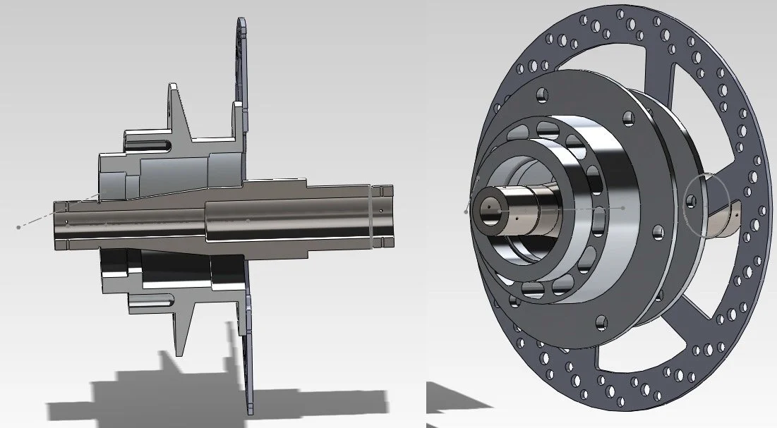
Final CAD models for Hub and Spindle Assembly
Hub and Spindle for Solar Car Front Wheels
Goal: redesign the hub and spindle in the solar car for the MIT Solar Car Team. Complete the project to race with new parts in the 2012 American Solar Challenge.
Project Dates: Oct 2011 - May 2012
More information about the team here
Complete report (link here) contains design process, strength calculations, fatigue analysis results, and machine drawings
Skills: GD&T, FEA Simulation, failure mechanics, error budget
-
At the start of the project, the existing system was plastically yielded whenever the car drove over a large bump. Further driving on the spindle increased loads on bearings, reducing bearing life and increasing energy lost to friction. The only fix was to replace the spindle. The fix was expensive, particularly during racing, because of the time needed to disassemble the spindle mid-race.
The project had two key tasks:
design a new hub and spindle that is strong enough to survive multiple races and could fit into the existing car. Races are typically over 1500 miles.
Determine the root cause of failure in the old spindle design, which was plastically deformed when the car drove over a large bump.
-
My key contributions (also detailed in the report):
Generated design concepts based on the system's mechanical functional requirements and team requirements.
Determined key part dimensions by analyzing strength and fatigue requirements, error budget, and fatigue analysis.
Select bearings for assembly by analyzing commercially available bearings for their bearing loads and expected lifetime.
Verified calculations and optimized weight through Finite Element Analysis.
Determined the failure root cause of the previous spindle design, as resulting from combined loading during bumps leading to a stress that exceeded the designed yield by 14%.
Created machine drawings for parts (GD&T) to be sent to a machine shop for manufacturing. Develop a complete parts list for assembling suspension. Parts produced and integrated into the car for the 2012 American Solar Challenge
Design For Combined Forces
Carroll Douglas's guide, ‘The Winning Solar Car, ' describes the suspension system's three external forces. My analysis results indicated that they needed to be considered together. While the old design accounted for all three loads, it did so separately. A combined load in the old design generated a resulting stress of approximately 114% of the yield stress. However, the new design now has a factor 2 safety margin, albeit at the expense of weight. The value chart was used to show that this trade-off was worth it.
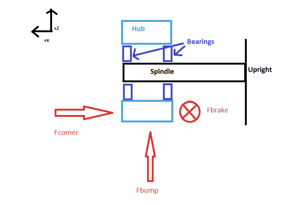
Sketch showing the three external forces felt by the hub and spindle system during driving.
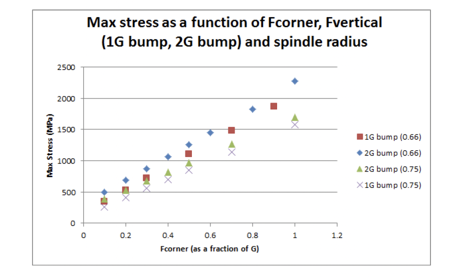
Summary of FEA results show that for the same F-corner force (horizontal axis), an increase in the vertical force also increased max stress in the spindle.
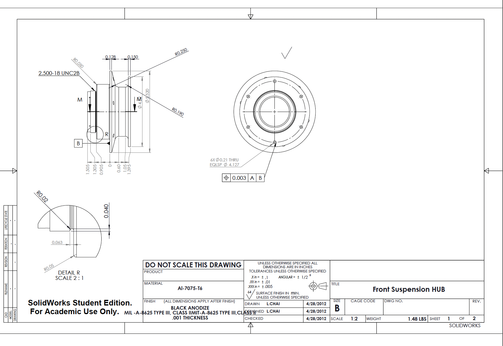
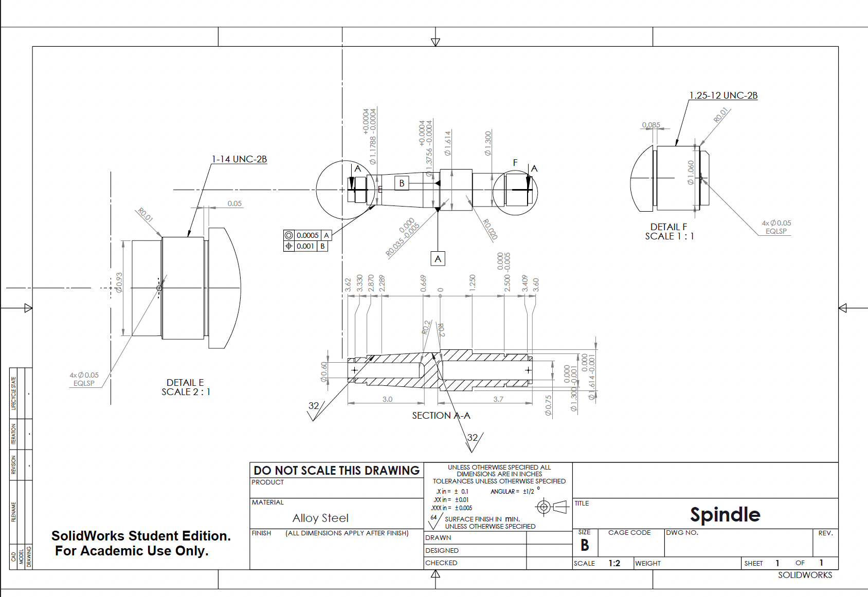
Machine Drawings for Hub and Spindle
Complete drawings and parts order for assembling new hub and spindle. Drawings were used by external machine shop to make part. System assembled for the 2012 American Solar Challenge.